[Top] [Prev] [Next] [Bottom]
This chapter provides information on installing the following optional upgrades:
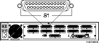
Follow these instructions to install external modems.
-
This cable is available from most computer equipment suppliers.
-
Use a 3-foot (90cm) cable that splits into two 50-pin high-density connectors to
connect to a U.S. Robotics Quad modem rack.

For modem configuration information, refer to one of the following:
Follow these instructions to add memory.
The PortMaster is shipped from the factory with four 30-pin, 1MB (1x30), 70-nanosecond-or-better single inline memory modules (SIMMs) of RAM installed. The memory can be increased to 8MB (2x30) or 16MB (4x30).
Caution ¯  Wear a grounding strap when handling the internal components of the PortMaster.
-
Turn the power switch off and disconnect the PortMaster from the power source.
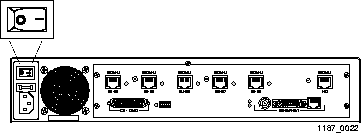
-
Lay the PortMaster down on a hard, flat, static free surface.
-
Ensure that the LEDs and ports are facing you.
-
Using a Phillips screwdriver, remove the screw from the top center of the PortMaster.
-
Remove the lid.
-
With both hands on the sides of the PortMaster, push the lid firmly until it slides
approximately 3 inches back. Lift the lid up and remove it.
-
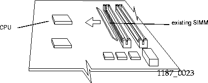
Locate the existing SIMM boards.
-
The SIMM boards are located in the upper right corner of the motherboard
approximately 3.5 inches to the right of the CPU.
-
Remove the existing SIMM boards.
-
Place your finger on the top center of the SIMM closest to the CPU and gently push
it in the direction of the CPU until the SIMM is free from its socket. Repeat with
each SIMM board until all four SIMM boards are removed.
-
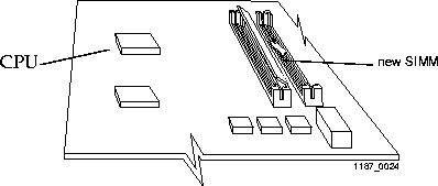
Insert the new SIMM boards.
-
Starting with the socket farthest from the CPU, slide a new SIMM board, gold side
down, into the socket at a 45-degree angle. Once the SIMM board is seated, place
your finger on the top center of the SIMM board and gently push it away from the
CPU until it clicks into place. Repeat with each SIMM board until all four SIMM
boards are inserted.
-
Replace the lid.
-
Slide the lid over the outside edges of the PortMaster, and slide it towards you
until it clicks into place.
-
Using a Phillips screwdriver, replace the screw in the top center of the PortMaster.
-
Connect the PortMaster to the power source and turn the power switch on.
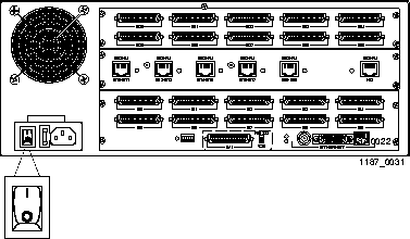
 Follow these instructions to install PortMaster expansion boards on the PM-2E,
PM-2ER, PM-2Ei-10I-U, and PM-2Ei-10I-ST.
Caution ¯  Wear a grounding strap when handling the internal components of the PortMaster.
-
Turn the power switch off and disconnect the PortMaster from the power source.
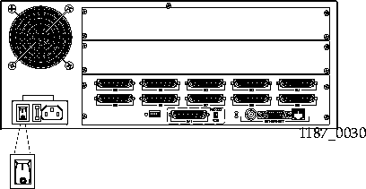
-
Lay the PortMaster down on a hard, flat, static free surface.
-
Ensure that the LEDs are facing you.
-
Using a Phillips screwdriver, remove the screw from the top center of the PortMaster.
-
Remove the lid.
-
With both hands on the sides of the PortMaster, push the lid firmly until it slides
approximately 3 inches back. Lift the lid up and remove it.
-
Ensure that a 60-pin ribbon has been installed in the center of the PortMaster motherboard.
-
If you are installing the MOD-101-U board, verify the board's revision number.
-
The PortMaster 2ER requires revision C or later of the MOD-101-U board. Any
version of the MOD-101-U board can be used in the PortMaster 2E and
PortMaster 2Ei.
-
Verify the position of the expansion board jumper.
-
The jumper pin is located between the two cable connectors on the expansion
board.
-
For an S10 through S19 expansion board, verify that the jumper connects the
pair of pins marked 1 to the middle pair of pins.
-
For an S20 through S29 expansion board, verify that the jumper connects the
pair of pins marked 2 to the middle pair of pins.

-
For an S10 though S19 expansion board, verify that the jumper connects the
pins 1 and 2.
-
For an S20 through S29 expansion board, verify that the jumper connects pins
2 and 3.

-
Using a Phillips screwdriver, remove the back cover plates from the rear of the PortMaster.
-
Attach the rear face plates with the screws provided.
-
Ensure that each face plate is aligned before tightening the screws.
-
Plug the 8-wire ribbon power cable and 60-wire ribbon bus cable into the front of each expansion board.

-
Replace the lid of the PortMaster case, and using a Phillips screwdriver, replace the screw.
-
Connect the PortMaster to the power source and turn the power switch on.
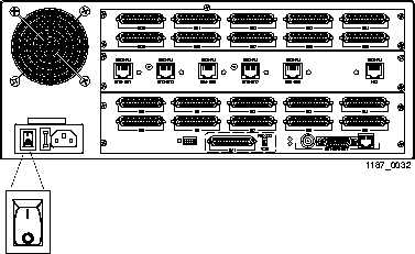
Follow these instructions to remove PortMaster expansion boards.
Caution ¯  Wear a grounding strap when handling the internal components of the PortMaster.
-
Turn the power switch off and disconnect the PortMaster from the power source.
-
Lay the PortMaster down on a hard, flat, static free surface.
-
Ensure that the LEDs are facing you.
-
Using a Phillips screwdriver, remove the screw from the top center of the PortMaster.
-
Remove the lid.
-
With both hands on the sides of the PortMaster, push the lid firmly until it slides
approximately 3 inches back. Lift the lid up and remove it.
-
Unplug the 8-wire ribbon power cable and 60-wire ribbon bus cable from the front of the expansion board.
-
Place the expansion board into an electrostatic discharge (ESD) bag.
-
To ship or store the expansion board, ensure that it is in a ESD bag, and cushion it
with foam in a sturdy box.
-
Using a Phillips screwdriver, reinstall the back cover plates shipped with the PortMaster.
-
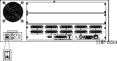
The PM-2E-30 and PM-2ER-30 are shipped with expansion boards installed and
have no back cover plates. In this case, leave the slot open until the expansion
board is reinstalled.
-
Replace the top of the PortMaster case, and using a Phillips screwdriver, replace the screw.
-
Connect the PortMaster to the power source and turn the power switch on.
[Top] [Prev] [Next] [Bottom]
spider@livingston.com
Copyright © 1998, Lucent Technologies. All rights
reserved.

 Wear a grounding strap when handling the internal components of the PortMaster.


 Wear a grounding strap when handling the internal components of the PortMaster.


 Wear a grounding strap when handling the internal components of the PortMaster.

