[Top] [Prev] [Next] [Bottom]
This chapter describes the Routing Information Protocol (RIP) operation on PortMaster products and provides sample network configurations that show how to configure each PortMaster product in the network.
This chapter discusses the following topics:
RIP is an interior routing protocol that uses a distance-vector algorithm to optimize routing. The distance-vector algorithm used by RIP for making routing decisions is based on the number of hops to a destination. The route with the least number of hops is considered to have the lowest cost. The number of hops is referred to as the route metric. A route with a metric greater than 15 is considered to be unreachable.
Although the more accurate link state technology of the Open Shortest Path First routing protocol (OSPF) is the most common interior routing protocol, RIP is still widely used on routers in TCP/IP and in Novell IPX networks as the primary method for the exchange of routing information.
When using RIP, routing updates can be turned on or off for individual interfaces on the PortMaster, and each interface can be configured as follows:
The examples in this section illustrate typical scenarios using RIP. Configurations are simplified to focus on the critical elements in each scenario. This section includes the following examples:
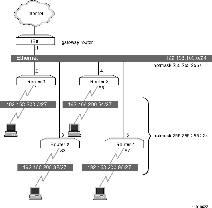
Figure 2-1 illustrates an appropriate implementation of subnetting. The example uses two class C addresses, one (192.168.100.0) for the local Ethernet segment and one (192.168.200.0) for dial-in users.
 Routing with Subnets
On the local Ethernet segment, an IRX at address 192.168.100.1/24 (netmask 255.255.255.0) is configured as the gateway router serving four PM-2ER-30s: Router 1 at address 192.168.100.2, Router 2 at 100.3, Router 3 at 100.4, and Router 4 at 100.5.
The second class C address, 192.168.200.0/27 (netmask 255.255.255.224) is divided into four subnets of 30 addresses each. Allowing for the use of the .0 subnet, this entire network is used for all the dial-in assigned pools. So the 192.168.200.0 is on 192.168.100.2, the 200.32 is on 100.3, the 200.64 is on 100.4, and the 200.96 is on 100.5. This is a convenient configuration because, with 30 dial-in ports on each PM-2ER-30, no addresses are wasted.
All the ports on the PM-2Es are configured for network dial-in, and routing is on by default-except during user configuration, when routing is set to off to ensure that it is disabled for dial-in clients.
Note ¯  On Ethernet interfaces, routing is off by default in ComOS 3.5 and earlier.
This example shows the configuration for the Ethernet port connecting the PortMaster IRX to the Ethernet network it shares with the PM-2ER-30s. Configuration of the WAN interface (which includes setting the S1 address, netmask, and destination, as well as setting a gateway to the Internet service provider) is not shown.
To configure the IRX, enter the following commands:
-
Set the Ethernet address:
Command> set ether0 address 192.168.100.1
Local (ether0) address changed from 0.0.0.0 to 192.168.100.1
-
Set the Ethernet netmask
Command> set ether0 netmask 255.255.255.0
Ether0 netmask changed from 0.0.0.0 to 255.255.255.0
-
Set the netmask for the 192.168.200.0 network:
Command> add netmask 192.168.200.0 255.255.255.224
Ether0 netmask changed from 0.0.0.0 to 255.255.255.0224
-
Set the Ethernet address:
Command> set ether0 192.168.100.2
Local (ether0) changed from 0.0.0.0 to 192.168.100.2
-
Set the Ethernet netmask:
Command> set ether0 netmask 255.255.255.0
Ether0 netmask changed from 0.0.0.0 to 255.255.255.0
-
Set the upstream gateway router:
Command> set gateway 192.168.100.1
Gateway changed from 0.0.0.0 to 192.168.100.1, metric = 1
-
Set the base IP address of the assigned address pool:
Command> set assigned 192.168.200.1
First assigned address changed from 0.0.0.0 to 192.168.200.1
-
Set the assigned address pool size:
Command> set pool 30
Assigned address pool size changed from 0 to 30
-
Add a static netmask to the netmask table:
Command> add netmask 192.168.200.0 255.255.255.224
New netmask successfully added
-
Save the configuration:
Command> save all
-
Set the Ethernet address:
Command> set ether0 192.100.3
Local (ether0) changed from 0.0.0.0 to 192.168.100.3
-
Set the Ethernet netmask:
Command> set ether0 netmask 255.255.255.0
Ether0 netmask changed from 0.0.0.0 to 255.255.255.0
-
Set the upstream gateway router:
Command> set gateway 192.168.100.1
Gateway changed from 0.0.0.0 to 192.168.100.1, metric = 1
-
Set the base IP address of the assigned address pool:
Command> set assigned 192.168.200.33
First assigned address changed from 0.0.0.0 to 192.168.200.33
-
Set the assigned address pool size:
Command> set pool 30
Assigned address pool size changed from 0 to 30
-
Add a static netmask to the netmask table:
Command> add netmask 192.168.200.0 255.255.255.224
-
Save the configuration:
Command> save all
New netmask successfully added
-
Set the Ethernet address:
Command> set ether0 192.100.4
Local (ether0) changed from 0.0.0.0 to 192.168.100.4
-
Set the Ethernet netmask:
Command> set ether0 netmask 255.255.255.0
Ether0 netmask changed from 0.0.0.0 to 255.255.255.0
-
Set the upstream gateway router:
Command> set gateway 192.168.100.1
Gateway changed from 0.0.0.0 to 192.168.100.1, metric = 1
-
Set the base IP address of the assigned address pool:
Command> set assigned 192.168.200.65
First assigned address changed from 0.0.0.0 to 192.168.200.65
-
Set the assigned address pool size:
Command> set pool 30
Assigned address pool size changed from 0 to 30
-
Add a static netmask to the netmask table:
Command> add netmask 192.168.1200.0 255.255.255.224
New netmask successfully added
-
Save the configuration:
Command> save all
-
Set the Ethernet address:
Command> set ether0 192.100.5
Local (ether0) changed from 0.0.0.0 to 192.168.100.5
-
Set the Ethernet netmask:
Command> set ether0 netmask 255.255.255.0
Ether0 netmask changed from 0.0.0.0 to 255.255.255.0
-
Set the upstream gateway router:
Command> set gateway 192.168.100.1
Gateway changed from 0.0.0.0 to 192.168.100.1, metric = 1
-
Set the base IP address of the assigned address pool:
Command> set assigned 192.168.200.97
First assigned address changed from 0.0.0.0 to 192.168.200.97
-
Set the assigned address pool size:
Command> set pool 30
Assigned address pool size changed from 0 to 30
-
Add a static netmask to the netmask table:
Command> add netmask 192.168.200.0 255.255.255.224
New netmask successfully added
-
Save the configuration:
Command> save all
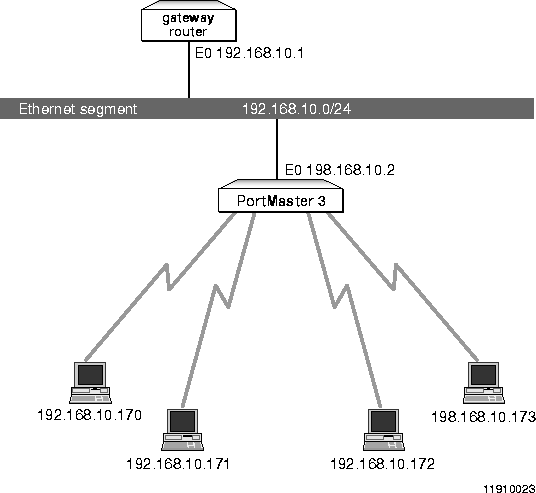
Proxy Address Resolution Protocol (ARP) is ARP for an IP address that is not local on the LAN. Figure 2-2 shows an example in which the PortMaster 3 Integrated Access Server acts as the proxy for dial-in users. The IP address of dial-in users must be in the same range as the Ethernet segment.
Figure 2-2 Proxy ARP

In addition to the regular configuration, enter the following commands to enable the PortMaster 3 to use proxy ARP for dial-in users:
-
1. Set the base address of the assigned address pool:
Command> set assigned_address 198.168.10.65
First Assigned address changed from 0.0.0.0 to 192.168.10.65
-
Set the size of the assigned pool of IP addresses:
Command> set pool 48
Assigned address pool size changed from 0 to 48
-
Save the configuration:
Command> save all
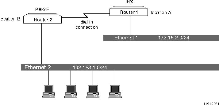
Figure 2-3 shows a simple network structure in which two locations are connected via a serial interface through a dial-in connection. Router 1, which has a connection to the Internet, is the only router connected to Ethernet 1. Router 2 is the only router connected to Ethernet 2. All data traffic between hosts on Ethernet 2 and the Internet must therefore use Router 1 as a gateway.
Figure 2-3 Simple Dial-In Router Connection
To make this connection possible, Router 2 must be configured so that hosts on Ethernet 2 can access the Internet via a dial-in PPP connection from Router 2 to Router 1, and Router 1 must be configured to accept a dial-in modem connection from Router 2.
Router 2 must broadcast RIP packets over the dial-in connection that contains route information about the Ethernet 2 network. Router 1 must listen for RIP packets over the dial-in connection to acquire the route information broadcast by Router 2.
In this example, a network user profile is configured for dial-in calls from Router 2. To keep the example focused, configuration of the WAN interface to the Internet is not considered. Router 1 is assumed to be a PortMaster IRX.
For more information, see the instructions for configuring dial-in connections in the Configuration Guide for PortMaster Products.
The complete configuration for Router 1 appears in the following box:
The following procedure shows the separate tasks involved in the configuration of Router 1:
-
Set the Ethernet interface address:
Command> set ether0 address 172.16.2.1
Local (ether0) changed from 0.0.0.0 to 172.16.2.1
-
Add a network user and password:
Command> add netuser prouter2 password ghrimpdezxt1
User successfully added
-
Set the network protocol to be used:
Command> set user prouter2 protocol ppp
Username: prouter2 Type: Dial-in Network User
Address: Negotiated Netmask: 255.255.255.0
Protocol: PPP Options: Quiet, Compression
MTU: 1500 Async Map: 00000000
-
Set the IP address of the remote router:
Command> set user prouter2 destination 192.168.1.1
Username: prouter2 Type: Dial-in Network User
Address: 192.168.1.1 Netmask: 255.255.255.0
Protocol: PPP Options: Quiet, Compression
MTU: 1500 Async Map: 00000000
-
Configure the router to receive RIP updates:
Command> set user prouter2 routing listen
Username: prouter2 Type: Dial-in Network User
Address: 192.168.1.1 Netmask: 255.255.255.0
Protocol: PPP Options: Quiet, Listen, Compression
MTU: 1500 Async Map: 00000000
-
Save the configuration and reboot:
Command> save all
Command> reboot
The show routes command issued on Router 1 now gives the following (partial) response:
The routes that Router 1 learned by listening to the RIP packets broadcast from Router 2 are shown in this router table.
This example assumes Router 2 to be a PortMaster 2E-30. The location table commands are used to set up the dial-out profile. Port S1 is used for the dial-out modem. To keep the examples focused on the routing configuration, global and host or user configurations are not shown.
For more information, see the instructions for configuring dial-out connections in the Configuration Guide for PortMaster Products.
The complete configuration for Router 2 appears in the following box:
The following procedure shows the separate tasks involved in the configuration of Router 2:
-
Set the Ethernet address on the interface connecting Router 2 to Router 1:
Command> set ether0 192.168.1.1
Local (ether0) changed from to 192.168.1.1
-
Set the gateway for this router:
Command set gateway 172.16.2.1
Gateway changed from 0.0.0.0 to 172.16.2.1
-
Add the location of Router 1 to the location table:
Command> add location loc_a
Location loc_a successfully added
-
Configure the location to dial on demand:
Command> set location loc_a on_demand
loc_a changed to On-Demand Dial
-
Set the protocol for the location:
Command> set location loc_a protocol ppp
loc_a protocol changed to ppp
-
Set the IP address of the location:
-
Note that the IP address of the location (destination) is the same as the IP address
of the gateway (see Step 2).
Command> set location loc_a destination 172.16.2.1
loc_a destination changed from 0.0.0.0 to 172.16.2.1
-
Set the interface to send RIP packets to loc_a:
Command> set location loc_a rip broadcast
loc_a rip changed from off to broadcast, no_listen
-
Associate the location with a dial group:
Command> set location loc_a group 1
loc_a group number changed from 0 to 1
-
Set the telephone number used for dialing to the location:
Command> set location loc_a telephone 15105551212
New telephone successfully set for location loc_a
-
Set the username used to authenticate on the remote host:
Command> set location loc_a username prouter2
New username successfully set for location loc_a
-
Set the password used to authenticate on the remote host:
-
The username and password entered here must also be present on the remote host
(in the user table, RADIUS, or other authentication mechanism).
Command> set location loc_a password ghrimpdezxt1
New password successfully set for location loc_a
-
Set the time period the line can be idle before the connection is dropped:
Command> set location loc_a idletime 20 minutes
loc_a idle timeout changed from 0 to 20 minutes
-
Set the number of dial-out ports to be used for this connection:
Command> set location loc_a maxports 1
loc_a maximumport count changed from 0 to 1
-
Assign the port to the dial-out group:
Command> set s1 group 1
Group number for port S1 changed from 0 to 1
-
Make the port available for dialing to the remote location:
Command> set s1 network dialout
Port type for S1 changed from Login to Network(dialout)
-
Reset the port:
Command> reset s1
Resetting port S1
-
Save changes and reboot:
Command> save all
Command> reboot
The show routes command issued on Router 2 now gives the following (partial) response:
[Top] [Prev] [Next] [Bottom]
spider@livingston.com
Copyright © 1998, Lucent Technologies. All rights
reserved.
 Routing with Subnets
 On Ethernet interfaces, routing is off by default in ComOS 3.5 and earlier.

