[Top] [Prev] [Next] [Bottom]
This chapter provides a brief overview of routing concepts and describes how the Lucent ComOS implements routing protocols. The chapter is intended as a quick refresher for those already familiar with network routing, and as an introduction for those with little or no knowledge of the standard protocols. See "About This Guide" for pertinent RFCs and some useful books.
You should understand this material before you configure your PortMaster. Refer also to the glossary for unfamiliar terms.
This chapter discusses the following topics:
Routing is the process of finding the route to a destination, and routing protocols determine how a router updates its route information. A router is attached to two or more networks, and its primary function is receiving IP packets through one network interface and forwarding them through another. The packets can travel through a number of routers before arriving at their final destination. Each router-to-router transmission is called a hop.
When a host sends an IP data packet to a destination host that is on the same network or subnet as the sending host, the packet goes directly to the destination host. If the destination host and sending host are on different networks or subnets, the packet goes to a router. The destination IP address contained in a data packet is the basic information that makes routing and delivery possible. The major differences between typical hosts and routers are
A router constructs a routing table containing a list of routes. Each route indicates the next place to which the router forwards a packet, to get it closer to a final destination. A route consists of the following information:
The IP address and routing table are used to route a data packet to a specific host on a network. In the case of Ethernet, an IP address must be translated to the physical, or media access control (MAC) address of the target host. This translation, or resolving of an IP address to a MAC address is carried out by the Address Resolution Protocol (ARP). The Reverse Address Resolution Protocol (RARP) translates in the opposite direction-that is, from a MAC address to an IP address.
In practice, a host broadcasts an ARP request over the Ethernet and listens for a reply. Other hosts on the Ethernet receive the request, and when one of them recognizes its own IP address, it replies with its MAC address. The requester then adds the IP address and MAC translation to its ARP cache for future use. In the case of a PortMaster, ARP cache entries expire after 15 minutes. Near the end of a 15-minute interval, the PortMaster sends another ARP request to refresh and maintain up-to-date cache entries.
ARP replies do not always have to be sent from the target host but can also be sent by a third party-such as a router-that knows the route information and acts as a proxy for the target. This process-known as proxy ARP-is supported by PortMaster products.
Static routes contain route information that does not respond to changes in network topology or condition. In spite of this inability to respond to change, static routes can be useful for stable networks or segments of networks that are not expected to change frequently.
Other possible uses for static routing are
If a network or a segment of a network has only one exit point, you need set only a default gateway to ensure that all packets bound for remote destinations get routed onto the Internet. A default gateway is also useful when you want to set up a gateway for packets that have no alternative route specified in the routing table.
When you specify a default gateway in a router configuration, all packets to destinations not found in the routing table are forwarded to that default gateway.
If a network has more than one possible route to a destination, or if the network is large or complex, or experiences frequent changes, dynamic or learned routing through the use of routing protocols is necessary. Routing protocols collect routing information, broadcast it dynamically, and update routing tables automatically to reflect network changes.
Dynamic routing adds a high degree of flexibility to the routing process by
The commonly used Routing Information Protocol (RIP) requires that a single netmask be used across the entire subnet. This limitation has a major impact on the routing of traffic among many networks. Regardless of the actual need for addresses, each subnet of the network must be assigned the same number of IP addresses.
The use of more than one subnet mask in a subnetted network is described in RFC 1812. A network using this method of subnetting is referred to as a network with variable-length subnet masks (VLSMs) because the network prefixes have different lengths. VLSM support allows more efficient use of TCP/IP addresses by allowing network designers greater freedom in assigning addresses.
On PortMaster products, VLSMs can be used for static routing without a routing protocol, or with a routing protocol that provides VLSM support, such as OSPF and BGP-4. VLSMs overcome the RIP limitation of having to use a single netmask across the network. RIPv1 does not send netmasks in its routing updates.
The advantages of VLSM over RIP are illustrated in Figure 1-1 and Figure 1-2.
Figure 1-1 and Figure 1-2 both show a network with the following topology:
In Figure 1-1, Router A exchanges RIP updates with Routers B and C. Because they are using RIP, Router A is unable to distinguish between the networks of Routers B and C. Router A sees both Router B and Router C as part of network 192.168.3.x, where x ranges from 0 through 255.
Figure 1-1 RIP Routing-without VLSMs
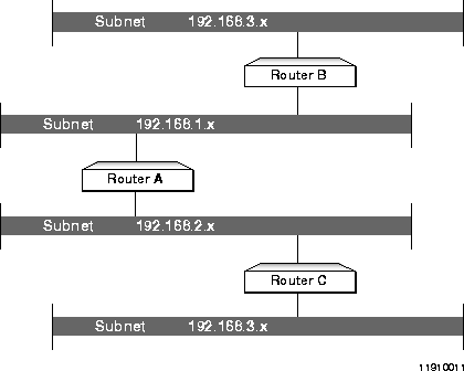
When data is directed from Router A to a 192.168.3.x address, Router A sends the packet to either Router B or Router C, depending on which router last provided a RIP update-making that last router appear to be the gateway for all network 192.168.3.x addresses. Hence, RIP cannot provide reliable routing in this kind of network.
Variable length subnet masking provides for more reliable routing. In the Open Shortest Path First (OSPF) network shown in Figure 1-2, Router A has both the IP address and the netmask information required to identify the unique set of addresses associated with the networks of Routers B and C. Router B's OSPF update states that its address is 192.168.3.65 and its netmask is 255.255.255.192. In other words, the subnet associated with Router B is 192.168.3.64/26, where 192.168.3.64 is the network prefix and the /26 represents the number of high-order bits in the netmask.
Figure 1-2 OSPF Routing-with VLSMs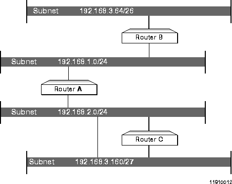
With this information, Router A can forward to Router B any IP traffic sent to addresses 192.168.3.64 through 192.168.3.127. Router C's address, 192.168.3.161, and network mask, 255.255.255.224-192.168.3.160/27-ensure that Router A can properly forward all traffic sent to addresses 192.168.3.160 through 192.168.3.191.
Variable-length subnet masking uses classless interdomain routing (CIDR) addressing. Table 1-1 lists the variable-length netmasks from 16 to 32, the CIDR representation form (/xx), and the hexadecimal and decimal equivalents. Refer to RFC 1878 for more information.
A PortMaster router gathers and maintains information in a routing table that enables the transmission of packets between networks. The routing table contains an entry for each identified route, and can be configured statically, maintained by the router dynamically through a routing protocol, or both.
PortMaster products support host routes and network routes. Variable-length subnet masks (VLSMs) and classless interdomain routing (CIDR) are also supported in ComOS release 3.5 and later, as is the more common use of a single subnet mask per network.
A PortMaster determines whether a packet is local or needs to be routed by examining the destination IP address of packets, and the IP address and netmask of the PortMaster interfaces. For example, if the PortMaster Ethernet address is 192.168.1.1 and the netmask is 255.255.255.0, then all hosts with addresses between 192.168.1.1 and 192.168.1.254 are deemed local hosts, and packets for these hosts do not require routing.
If a packet requires routing, the routing table is consulted, with one of the following results:
The PortMaster maintains a routing table, and each entry includes some or all of the following information, depending on the routing protocol used:
-
Routing protocol used
-
Destination prefix
-
Netmask length
-
Gateway
-
Source of routing data
-
Route status flags
-
Metrics
-
Interface
The longest prefixes in a routing table entry are checked first. If no route is found, the learned gateway (if one exists) is used; otherwise the primary gateway is used. If no route is found, the packet is discarded.
Static routes are never overwritten with learned, or "dynamic," routes. However, if a default gateway with a better metric than the primary gateway is learned and default routes are being listened for, the new gateway is set as the learned gateway. In addition, the learned gateway is replaced if a default gateway with a lower metric is found.
Routes are valid only for active interfaces. If an interface becomes unreachable, all routes that go through the interface are examined. If the specified gateway is available through another interface, the route is moved to the active interface. Otherwise, the routing table entry is marked as obsolete.
Table 1-2 shows an example of a PortMaster routing table.
Table 1-3 describes the routing table flags.
Routing protocols supported by the Lucent ComOS include the following:
The selection of appropriate routing procedures and protocols for specific network applications depends primarily on the following:
The Routing Information Protocol (RIP) is an interior routing protocol that uses a distance-vector algorithm to optimize routing. It is widely used by routers in TCP/IP networks and Novell IPX networks.
PortMaster RIP updates for each interface can be configured to broadcast routing updates, listen for routing updates, both, or neither. RIP routes are updated in the following ways:
The Open Shortest Path First (OSPF) routing protocol is designed for a hierarchical network structure and is generally organized in a form similar to that shown in Figure 1-3.
The community of routers, usually owned and managed by a single group as illustrated in Figure 1-3, is called an autonomous system (AS). OSPF divides the world into two domains-within the autonomous system and external to the autonomous system. The autonomous system itself is divided into a central, or backbone area (area 0) to which all other areas are connected, and other (nonzero) numbered areas
Figure 1-3 OSPF Network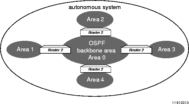
Each OSPF area has one or more network address/netmask pairs and is identified by a 32-bit area number. An area is a contiguous set of routers sharing network segments between them. An area must be one of the following types, depending upon the routing information that it uses:
The following terms are used to describe relationships in an OSPF network:
Routers in an autonomous system belong to one or more of the following categories:
OSPF routes are divided into types described in Table 1-6.
When comparing routes of the same type, the rules given in Table 1-7 show which route is better-has the lowest cost.
Note ¯  Currently, the Border Gateway Protocol (BGP) runs only on PortMaster IRX routers and the PortMaster 3. Because a full BGP routing table for the entire Internet requires 7MB of memory, be sure to upgrade your IRX or PortMaster 3 to 16MB of memory.
The concept of a hierarchical network structure was introduced in "OSPF" on page 1-14, along with a description of an autonomous system. In contrast to the OSPF interior routing protocol, which was designed for routing within an autonomous system, the Border Gateway Protocol (BGP) is an exterior routing protocol. BGP version 4, described in RFC 1771, and further defined in version 5 of the BGP-4 Internet Draft RFC of January 1997, was designed for routing between autonomous systems. To use BGP, each autonomous system must have an autonomous system identifier. You obtain autonomous system identifiers from the Internet Network Information Center (InterNIC).
BGP can be thought of as the "glue" that holds the Internet together. Consequently, BGP routing tables can contain tens of thousands of routes. This number is increasingly rapidly as the Internet expands.
The primary purposes of BGP are to allow different autonomous systems to share routes and to connect in redundant ways, controlled by policy and protocol design, so that routing loops are not formed.
Figure 1-4 illustrates companies in five autonomous systems that use BGP as an exterior routing protocol.
Figure 1-4 Example of Linked Multiple Autonomous Systems
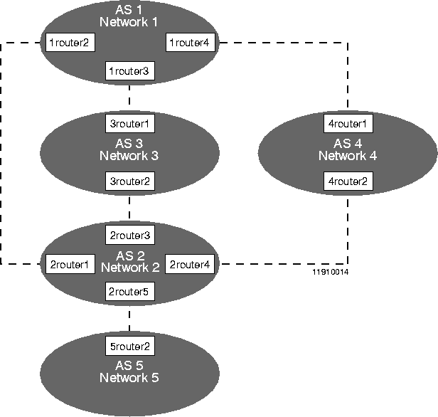
Autonomous system AS 1 advertises Network 1; autonomous system AS 2 advertises Network 2, and so on. A pair of BGP routers is located between each pair of autonomous systems. For example, 1router4 and 4router1 are located between AS1 and AS4.
BGP does not advertise a simple metric representing cumulative link bandwidth costs, as do protocols such as OSPF. Instead, BGP advertises only a path through zero or more autonomous systems, the attributes of the path, and sets of destinations reachable at the end of the path. Sets of destinations are called the network layer reachability information (NLRI). The combined bundle of the path, attributes, and NLRI is called a BGP route. Based on BGP route information, each BGP router executes policy decisions to choose the best route to a final destination.
AS 1 has the following information about paths to Network 5:
BGP does not broadcast route information to all listeners as do RIP and OSPF. Instead, each router running BGP must be configured for every other BGP router with which it needs to communicate. Routers that send BGP messages to each other are called BGP speakers, and each pair of BGP speakers that communicate with each other are called peers. Peers are explicitly configured by the PortMaster administrator.
Peers are called internal when they belong to the same autonomous system. When peers belong to other autonomous systems, they are referred to as external peers. BGP treats internal and external peers differently in many details. In particular, unless either route reflection or BGP confederations are configured, all internal peers in a single autonomous system must be fully meshed (directly peered) with each other. For example, if AS 25 has four internal peers (A, B, C, D), then it has six pairs of internal peers (AB, AC, AD, BC, BD, CD). If you are using route reflection or confederations, the routers are partially meshed.
BGP requires that all BGP peers within an autonomous system be linked to each other-or fully meshed. As a result, when a BGP peer learns an external route-path attributes and destination-it does not forward this route to the other BGP peers because they already have it. As the number of peers increases in an autonomous system, the number of required links can become large. For example, an autonomous system with 20 peers requires 190 links.
You can reduce the number of BGP peer links by dividing the autonomous system into smaller autonomous systems called confederation member autonomous systems (CMASs). RFC 1965 describes CMASs. If the 20-peer autonomous system is subdivided into a confederation with five CMASs of four peers each, the total number of links is reduced from 190 to 35. This reduction simplifies management of the autonomous system, and reduces message traffic.
Like BGP autonomous system confederations, route reflection (described in RFC 1966) allows the clustering of peers and reduces the number of links that are otherwise required for a fully meshed autonomous system. Although route reflector clusters are configured differently from CMASs, the functional difference between the two is that route reflectors in each cluster maintain path and attribute information across the entire autonomous system. In this way, the autonomous system still functions like a fully meshed autonomous system.
Route reflection is useful when you want to reduce the traffic and CPU overhead of a fully meshed system. However, confederations allow for policy changes and control across the confederation boundaries within an autonomous system, while route reflection requires the use of identical policies on all internal peers. Therefore, if you want to fine-tune routing within the autonomous system, confederations offer a better solution.
A BGP speaker can forward to its peers information learned from other peers, as well as originate information into the BGP Internet. BGP originates to its peers only routing information explicitly indicated and supported by the interior routing protocols in use-OSPF, RIP, static routes, or directly attached routes. These special advertisements are called summarizations, and must be explicitly configured.
A summarization is advertised only when an explicit route in that summary is supported through a non-BGP source such as OSPF, RIP, a static route, or a directly attached route-Ethernet, Frame Relay, T1, and so on. The supported route must be more specific than or as specific as the route in the summary. For example, a default route to 0.0.0.0/0 cannot support a summary.
On the PortMaster, all static routes, either configured or learned via RADIUS, can be summarized automatically through propagation. You can define a rule for propagating-translating and advertising-all static routes into BGP.
When a PortMaster learns multiple routes to a destination, it uses the following route precedence rules for selecting the preferred path, in order from highest to lowest:
-
1. Static routes
-
2. Default routes learned via BGP
-
3. Routes learned from BGP external peers
-
4. Routes learned from OSPF and RIP. Routes with the lowest computed hop count are preferred. In the case of a tie, the PortMaster uses the following order of preference, in order from highest to lowest:
a. OSPF intra-area routes
b. OSPF interarea routes
c. OSPF external Type 1 routes
d. OSPF not-so-stubby-area (NSSA) type 1 routes
e. OSPF external Type 2 routes
f. OSPF NSSA Type 2 routes
g. RIP routes
-
5. Routes learned from BGP internal peers
With propagation, you can translate routes from one routing protocol into another-for example, RIP into OSPF. Normally, the route does not include an explicit hop count, and the PortMaster computes a hop count for you. This computed hop count minimizes the chances of routing loops occurring between routing protocol boundaries. However, if you choose to override the automatic hop count computation and specify an explicit hop count, you should consider using propagation rules with route filters to ensure that routing loops are not created.
Figure 1-5 shows four networks connected by four PortMaster IRX routers.
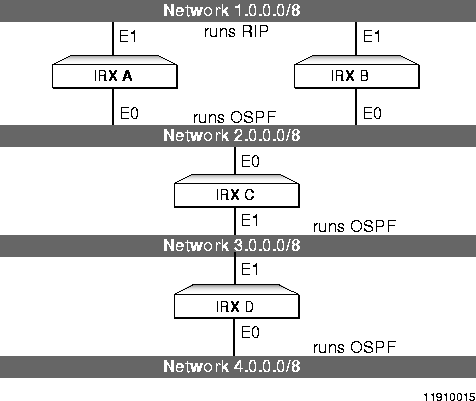 Propagation Rule
For these networks, assume a propagation rule configured on both IRX A and IRX B to always translate OSPF routes into RIP routes with a hop count of 1. As a result, both IRX A and IRX B advertise network 4.0.0.0 into RIP with a hop count of 1. IRX B has a choice of routes to network 4.0.0.0 as follows:
-
The one-hop-count RIP route via IRX A
-
The multihop OSPF route via IRX C
The automatic preference rules of the ComOS favor the RIP route for IRX B, and IRX A makes exactly the same choice. As a result, routers IRX A and IRX B point to each other for routes to network 4.0.0.0, thereby creating a routing loop.
This problem is not unique to the way the ComOS determines its route preferences. Mechanisms that translate routing protocols using a fixed metric for all routes, or that allow routes from one protocol-such as OSPF-to be always preferred over another-such as RIP-share the same style of routing loop problems across a routing protocol boundary. These problems are the intrinsic result of using fixed metrics for route advertisement. Consider the example shown in Figure 1-5 with the RIP and OSPF routing protocols reversed. If OSPF routes are always preferred over RIP, IRX A and IRX B have exactly the same problem in choosing a route to network 4.0.0.0. They always choose each other.
To avoid creating routing loops, use a routing protocol input filter. With such a filter, you can indicate on IRX A and IRX B that routes coming from RIP are accepted on a RIP-running Ethernet only and are translated into OSPF. Similarly, on an OSPF-running Ethernet, you can choose to propagate into RIP only those routes from the OSPF side of the network.
If multiple routers in your network perform route propagation using fixed metrics, you can avoid routing loops by applying route filters with your propagation rules.
[Top] [Prev] [Next] [Bottom]
spider@livingston.com
Copyright © 1998, Lucent Technologies. All rights
reserved.


 Currently, the Border Gateway Protocol (BGP) runs only on PortMaster IRX routers and the PortMaster 3. Because a full BGP routing table for the entire Internet requires 7MB of memory, be sure to upgrade your IRX or PortMaster 3 to 16MB of memory.

 Propagation Rule