[Top] [Prev] [Next] [Bottom]
This appendix offers case studies of some typical routing problems experienced by Lucent customers and the solutions provided by the Lucent technical support team. The chapter begins with a discussion of troubleshooting programs you can use to help resolve routing problem.
This chapter discusses the following topics:
This section describes some of the most useful tools for troubleshooting a routing problem or a suspected routing problem. For more information on these and other network troubleshooting or debugging tools, refer to the Configuration Guide for PortMaster Products, the Command Line Administrator's Guide, TCP/IP textbooks, and your host's system administration manuals.
Troubleshooting tools discussed in this section include the following:
The ping command, available as part of the PortMaster command set, sends 10 Internet Control Message Protocol (ICMP) echo request packets to the target and listens for an ICMP echo reply. The ping command, also part of the UNIX operating system (and other operating systems), is fairly common on networked hosts and on routers. Because it is simple to use and checks end-to-end connectivity, ping is generally the best first choice to use for isolating and resolving a routing problem.
The PortMaster ping command is used as shown (with the system response) in the following example:
Command> ping 192.168.16.0
192.168.16.0 is alive
If the ping sent to the target is not returned, the response is
no answer from 192.168.16.0
When used with the -s option, some versions of ping return statistics on packets sent and the time elapsed for the ping round trip, as in the following abbreviated example:
Command> ping -s 192.168.16.0
PING 192.168.16.0: 56 data bytes
64 bytes from 192.168.16.0: icmp_seq=0 ttl=255 time=12 ms
64 bytes from 192.168.16.0: icmp_seq=1 ttl=255 time=12 ms
64 bytes from 192.168.16.0: icmp_seq=2 ttl=255 time=12 ms
This PortMaster command allows you to see packet information as it passes through a PortMaster product. You use filters to define which packets you want to display. Ptrace does not display ICMP or User Datagram Protocol (UDP) packets that originate on the PortMaster itself.
The ptrace command is frequently used in conjunction with ping. Typically, you open a Telnet session into a PortMaster, activate the ptrace command with an appropriate protocol filter, such as TCP, ICMP, UDP, or IPX, and trace the ping packets as they arrive at or pass through the PortMaster. The following example shows how to configure a PortMaster product to use ptrace with an ICMP packet filter:
Command> add filter test
New Filter successfully added
Command> set filter test 1 permit icmp
Filter test updated
Command> set console
Setting CONSOLE to admin session
Command> ptrace test
Packet Tracing Enabled
Ptrace output of pings arriving at a PortMaster appear as follows:
icmp from 192.168.148.1 to 10.0.0.3 type Echo Request
icmp from 192.168.148.1 to 10.0.0.3 type Echo Request
icmp from 192.168.148.1 to 10.0.0.3 type Echo Request
Ptrace output of pings passing through a PortMaster appear as follows:
icmp from 192.168.148.1 to 10.0.0.15 type Echo Request
icmp from 10.0.0.15 to 192.168.148.1 type Echo Reply
To stop the ptrace, issue the following commands:
Command> ptrace
Packet Tracing Disabled
Command> reset console
Console RESET
Traceroute is another useful troubleshooting tool included in the PortMaster command set. It is also widely available with UNIX and other operating systems. While ping checks only the end-to-end connectivity, traceroute tries to identify each hop in the path to a destination by sending IP packets with the time-to-live (TTL) set incrementally from 1 to a maximum of 30. It prints the addresses that return ICMP TTL expired packets.
Use the traceroute command as shown, with response, in the following example:
Command> traceroute 172.16.1.2
traceroute to (172.16.1.2), 30 hops max
1 192.168.96.2
2 192.168.1.3
3 172.16.1.2
Traceroute (UDP) takes its source address from the interface through which it exits, while ping (ICMP) takes its source address from the Ether0 interface. When you use traceroute and ping together, if traceroute reaches its target and ping does not (or vice versa), check routing to see if the two addresses are being routed differently. This is a common routing problem over Frame Relay connections
This section includes the following case studies:
This case illustrates some common problems that arise when you configure host routes and network routes. The discussion assumes you are running ComOS 3.5 or later and that you have set the user-netmask to on (see set user-netmask in the Command Line Administrator's Guide).
As shown in Figure A-1 , an Internet service provider (ISP) using a PortMaster 3 Integrated Access Server (labeled Router1) receives dial-up connections from a remote user on a PC and from another PortMaster (labeled Router2) serving a corporate LAN. Typical problems in this situation include the following:
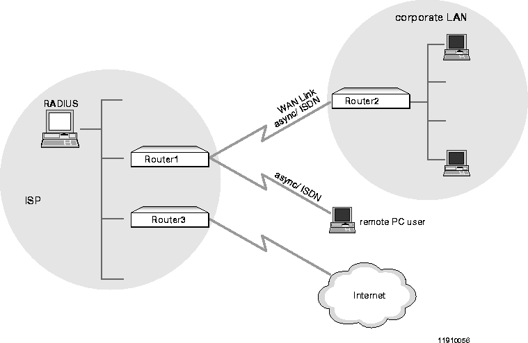 Host Routing versus Network Routing
Symptoms experienced by Router2 on the corporate LAN or the remote PC user due to configurations problems described previously include the following:
To verify that the remote PC user or Router2 is in fact connected, the ISP administrator can send a ping or traceroute command to the device. A show all, show ports, or show sessions command can also reveal whether these devices are connected.
If the administrator can verify that the connection is active, a show routes command or a show table user command entered on Router1 (if users are added locally) provides information about the nature of the session and the netmask of the device on the other end. Information about users maintained in the RADIUS database can be viewed on the RADIUS server.
For the remote PC user, the netmask in the user entry (locally or on the RADIUS server) must be /32 (255.255.255.255) to indicate that it is a single host IP address. When the PC establishes a connection with Router1, a show routes command on Router1 must display a host local (HL) flag associated with the route to the PC.
For Router2, the netmask in the user entry (locally or on the RADIUS server) must reflect the size of the network behind it. When Router2 establishes a connection with Router1, a show routes command on Router1 must display a network local (NL) flag associated with the route to the Router2.
If the netmask for Router2 is /32 netmask (255.255.255.255), Router1 might treat Router2 as a host. If it does, Router1 will not route to any of the hosts on Router2's network. Router2, also, will not route for any of the hosts on its network; it will route only for itself. Conversely, anything other than a /32 netmask for the remote user on the PC can cause Router1 to treat the PC as a router with a network behind it.
If users are maintained locally, set the appropriate netmask for Router2 on Router1, and enter the command set user-netmask on to help Router1 distinguish a host from a router. For the remote PC user, set the user netmask to /32 (255.255.255.255). Because the netmask table defaults to a full class C, you must set the user netmask when adding users locally. (See set user-netmask in the Command Line Administrator's Guide.)
If users are maintained in a RADIUS database, use the Framed-IP-Netmask reply item to configure the appropriate netmask associated with Router2 (RADIUS defaults to a /32 netmask). Refer to the RADIUS Administrator's Guide for instructions about setting Framed-IP-Netmask. Because the RADIUS server defaults to a 255.255.255.255 netmask, you need not set a netmask in the user entry for the dial-up PC.
If the netmask for the PC is not 255.255.255.255, and user-netmask is on, the ISP will experience severe Proxy ARP and routing problems on Router1. For effective network operation, the remote PC must be configured with a /32 netmask, and the netmask for Router2 must be correctly configured on the RADIUS server.
Note ¯  set user netmask and set user-netmask are separate commands.
This case illustrates the kinds of problems experienced when the gateway router is improperly configured.
Figure A-2 shows the network structure for this case.
Configuring the Gateway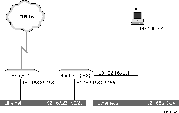
The specifics of this configuration are as follows:
The host on Ethernet 2 is not able to communicate with the Internet
From Host, a ping to Router 1 shows that Router 1 is active. A ping to Router 2 generates no response. A ptrace with an ICMP packet filter set up via Telnet to Router 1 shows the ping from Host to Router 1 and the ping from Host to Router 2, but no return ping from Router 2 to Host. This behavior points to a problem with the routing setup on Router 2.
When the source of the problem is isolated as shown here, a show routes command entered on Router 2, provides the following (partial) response:
The output clearly shows that in the static route the destination (192.168.2.0) is correct, but the gateway route was entered incorrectly as 192.168.20.195 instead of 192.168.26.195, the Ether1 interface address on Router 1.
The solution to this problem is to issue the following commands on Router 2:
Command> delete route 192.168.2.0
Route successfully deleted
Command> add route 192.168.2.0 192.168.26.195 1
New route entry successfully added
Command> save all
After completing the configuration change, repeating the ping and ptrace testing confirmed that routing was functioning correctly.
This case illustrates the kinds of problems experienced because of invalid use of subnetting.
Figure A-3 shows the network structure for this case.
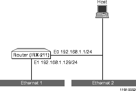 Configuring Subnets
The configuration information in this case is as follows:
The PortMaster IRX-211 cannot not communicate with Host, and Host cannot communicate with Ethernet 1.
An examination of the PortMaster IRX-211 configuration shows that the two Ethernet interfaces are on the same subnet of the same network. This is an invalid configuration; the two Ethernet interfaces must be on different networks or subnets.
One solution is to use a 26-bit netmask to divide the Class C IP address into four subnets of 62 host addresses each. In this way, two of the available subnets are used, one for Ethernet 2 and one for Ethernet 1, leaving an additional two subnets for future use. The IP addresses originally assigned to the Ether0 and Ether1 interfaces are then in different subnets and need not be renumbered.
Correct the netmasks for the interfaces with the following commands:
Command> set ether0 netmask 255.255.255.192
ether0 netmask changed from 255.255.255.0 to 255.255.255.192
Command> set ether1 netmask 255.255.255.192
ether1 netmask changed from 255.255.255.0 to 255.255.255.192
Command> save all
Saving global configuration
Saving ports
User table successfully saved
Hosts table successfully saved
Static route table successfully saved
Location table successfully saved
SNMP table successfully saved
Filter table successfully saved
Netmasks table successfully saved
Modem table successfully saved
New configurations successfully saved.
Command> reboot
Note ¯  You must reboot the PortMaster router to rebuild the routing table.
This case involves some confusion about IP numbered and unnumbered interfaces. Figure A-4 shows the network structure for this case.
Configuring Unnumbered Interfaces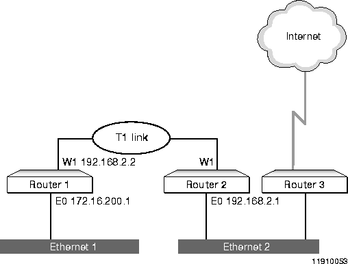
Device configurations in this case are as follows:
Router 1 and Router 2 cannot communicate.
An examination of the configurations shows that on Router 1 the W1 port is set to create a numbered interface, while the W1 port on Router 2 is not configured to create an interface.
In this situation, the solution is to configure unnumbered interfaces for the W1 ports on Router 1 and Router 2 by entering a series of commands on both routers.
Use the following commands on Router 1:
Command> set w1 address
Port W1 address changed from 192.168.2.2 to 0.0.0.0
Command> set w1 netmask 0.0.0.0
W1 netmask changed from 0.0.0.0 to 0.0.0.0
Command> set w1 destination 192.168.2.1 255.255.255.0
Port destination changed from 0.0.0.0 to 192.168.2.1
Command> save all
Saving global configuration
Saving ports
User table successfully saved
Hosts table successfully saved
Static route table successfully saved
Location table successfully saved
SNMP table successfully saved
Filter table successfully saved
Netmasks table successfully saved
Modem table successfully saved
New configurations successfully saved.
Command> reboot
Use the following commands on Router 2:
Command> set w1 address
Port W1 address changed from 0.0.0.0 to 0.0.0.0
Command> set w1 netmask 0.0.0.0
W1 netmask changed from 0.0.0.0 to 0.0.0.0
Command> set w1 destination 172.16.200.1 255.255.255.0
Port destination changed from 0.0.0.0 to 172.16.200.1
Command> save all
Saving global configuration
Saving ports
User table successfully saved
Hosts table successfully saved
Static route table successfully saved
Location table successfully saved
SNMP table successfully saved
Filter table successfully saved
Netmasks table successfully saved
Modem table successfully saved
New configurations successfully saved.
Command> reboot
In this case study, two Ethernet networks in two OSPF areas are incorrectly connected over a WAN link.
To conserve IP addresses, administrators typically do not assign IP addresses to the device serial interfaces on the WAN link-in this case, between OR-HS2 and OR-HS1. Instead, the destination address for the serial interface on each router is set to the Ether0 address of the router on the opposite end of the link. For example, in Figure A-5 the Ethernet port 10.0.0.2 is set as the destination for S1 on OR-HS2 and the Ethernet port 192.168.1.1 is set as the destination for OR-HS1.
OSPF is enabled on the S1 and Ethernet interfaces on both devices, and the OSPF area ranges are set as shown in "Configuration Information."
Note ¯  Although this example uses Lucent OR-HS devices on Ethernet, this problem can occur on any network type or router in a similar configuration.
Propagating OSPF over a WAN Link (Incorrect)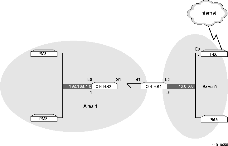
The incorrect configuration settings for OR-HS2 appear in the following box:
The incorrect configuration settings for OR-HS1 appear in the following box:
OSPF is not being propagated between Area 1 and Area 0. Output of the show ospf neighbor command on either of the OR-HS devices reveals that neither is the OSPF neighbor of the other, and the if config command shows that OSPF is not enabled on serial ports.
When you enable OSPF, it applies an area to each port that falls within the range you set for it. Because the S1 port on OR-HS2 is directly connected to the 10.0.0.0 network (which is its destination), it is outside of the range set for Area 1, and OSPF cannot assign an area to the S1 port.
To correct this problem, you assign an IP address to the S1 port on OR-HS2 (192.168.2.1), and you assign an IP address to the S1 port on OR-HS1 (192.168.2.2). Now the address of the S1 port on OR-HS2 falls within the range of Area 1, so it is assigned to the area; and the address of the S1 port on OR-HS1 also falls within the range of Area 1, so it, too, is assigned to the area. These two routers can now negotiate OSPF back and forth across the WAN link.
Figure A-6 illustrates this address assignment scheme and is followed by the correct configuration for each router in this example. See also "Propagating OSPF over a Single WAN Link" on page 3-12 for a full description of the configuration.
Propagating OSPF over a WAN Link (Correct)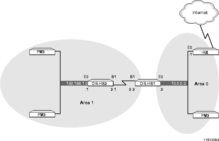
The correct settings for OR-HS2 appear in the following box:
The correct settings for OR-HS1 appears in the following box:
[Top] [Prev] [Next] [Bottom]
spider@livingston.com
Copyright © 1998, Lucent Technologies. All rights
reserved.
 Host Routing versus Network Routing
![]() set user netmask and set user-netmask are separate commands.
set user netmask and set user-netmask are separate commands.
![]() You must reboot the PortMaster router to rebuild the routing table.
You must reboot the PortMaster router to rebuild the routing table.


